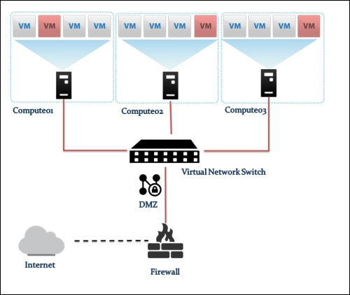
Providing layer two connectivity to running instances in your private OpenStack cloud infrastructure requires more advanced virtual/physical switching configuration. You may raise this question: how could an instance in a private tenant "virtual" network connect outside and "ping the world"? Or, is there a way that allows a virtual machine running within tenant B to establish a connection with another one running in a different network within a different tenant C? As you can see, designing complex structures to answer the previous questions is not a simple matter.
Typically, Open vSwitch is a virtual switch that embodies the emerging concept of Software Defined Networking (SDN). Overall, the former concept aims to treat networks as programs that can be easily deployed and provisioned.
Moreover, what makes it the cat's meow is the ability to integrate a virtual switching environment within a physical one due to many supported features, including:
802.1q VLAN tagging
STP
OpenFlow and sFlow protocols support
Tunneling protocol support, including VxLAN, GRE, IPsec, GRE over IPSec, and VXLAN over IPsec
NIC bonding support LACP
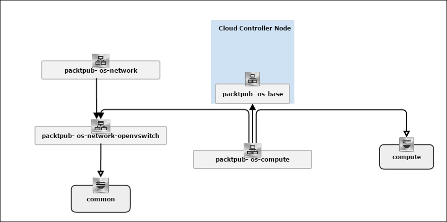
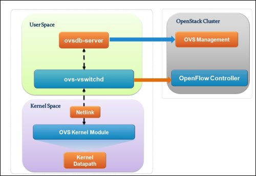
Let's see how Open vSwitch is architected in a simplistic figure:
The overall architecture should be straightforward to understand:
Open vSwitch daemon (ovs-vswitchd): This is essentially a program running within the Linux kernel model in each host, which imposes how the flow would be switched or forwarded
Open vSwitch database (ovsdb-server): An Open vSwitch database is created in each host running ovs daemon to maintain the virtual switch configuration
OVS Kernel module: This is a data path where all packets are forwarded and tunneled or encapsulated and decapsulated
Similar to the Linux Bridge plugin, Open vSwitch relies on the bridge and its kernel modules. What makes the difference are the unique virtual devices that are created in the compute host once you start using the OVS plugin. OVS uses more than one bridge; each one will have a port with the same name as the bridge itself by default. On first glance, we can enumerate bridges used by OVS compared to the Linux Bridge plugin:
br-int: This is the integration bridge with the port called br-int by default. Basically, instances, DHCP servers, routers, and switches will be connected to br-int. It is imperative to notice that it is not possible to connect the tap devices (the virtual machine network interface) directly to the integration bridge; the reason behind this is the use of iptables rules on tap interfaces whereas Open vSwitch does not support security groups by matter of design. IP tables are applied directly on tap devices. So, what will be the magic link? The solution promotes the usage of simple Linux bridges that connect to the integration bridges in turn. Eventually, tap interfaces will offer a route for filtering to the kernel.
br-ex: This is the physical bridge (the provider bridge another naming fashion) that enables instances to communicate with the physical network on a given interface ethX (X is the numbered physical NIC of the host). The br-ex bridge can be created and associated within an ethX host physical interface, which allows both ingress and egress traffic to the physical network environment.
br-tun: This is a bit confusing if you start forming a picture of how many bridges an Ethernet frame will need to travel from the external network to the virtual machine network interface. To make it simple, we will consider br-tun as a form of a physical bridge but for a different purpose. If you use Neutron to create tunnels, a tunnel bridge named br-tun will be created to handle and translate VLAN-tagged traffic coming from the integration bridge into GRE or VXLAN tunnels. Flow rules will be installed and applied at this stage.
However, how should br-int and br-tun, for example, connect? Eventually, integration bridges will connect to either tunnels or physical bridges by means of virtual patch ports. For example, a patch-tun patch tunnel port connects an integration bridge to the tunnel one. What about the connection between the integration bridge and the Linux Bridge carrying the tap interface? To answer this question, you can imagine two interconnected switches via trunk; physically, they are connected by means of patch cables. Open vSwitch does the same; each Linux bridge in the virtual environment acquires a virtual interface veth.
Tip
It is imperative that you remember once you implement OVS, every host in your OpenStack environment, including cloud controllers, compute nodes, and network nodes, must have its own integration bridge as well as a physical/tunnel bridge.
Let's resume with the number of virtual type networking devices that are involved when we implement OVS:
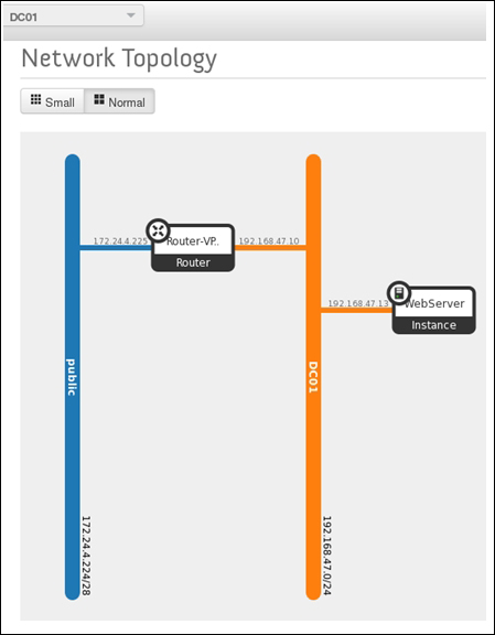
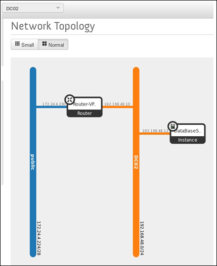
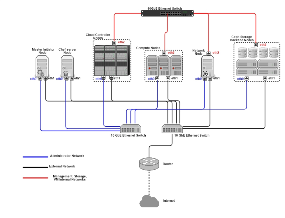
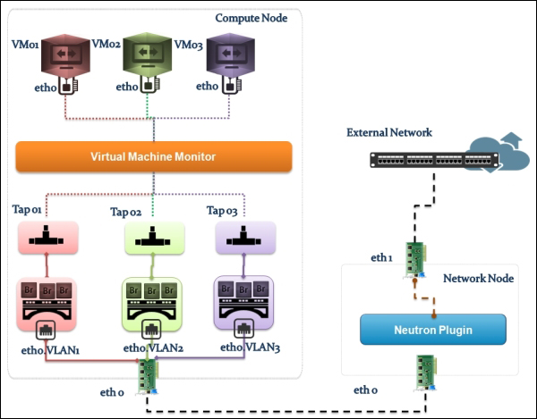
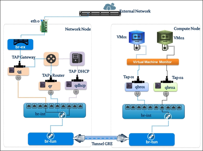
Now, let's follow the Ethernet frame traveling from the physical network to a virtual machine interface. We will use a more sophisticated example by showing an implementation involving a GRE network setup in an OpenStack network environment. The next visual representation shows a compute01.packtpub compute node connected to a network01.packtpub network node. Both nodes are connected by means of the br-tun tunnel bridge, as shown in the following figure:
Let's start with the compute node, and check its virtual switch configuration using the next command line:
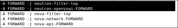
Starting from the virtual machine network interface, the Ethernet packet starts its trip from the instance connected to the tap interface device on the compute node tap6d6ee47e-04. Then, it drops by the Linux Bridge device attached to it via the qbr6d6ee47e-04 virtual Ethernet cable. Let's take a closer look and see how packets are processed. Remember that attaching the tap interface to the Linux Bridge instead of the integration bridge is necessary because of the support of firewall rules' compatibility. We should then expect the implication of certain iptables rules at this stage:
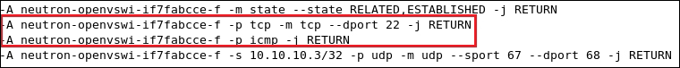
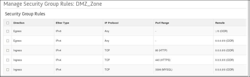
We can check where our security rules are realized. We see clearly that the neutron-openvswi-sg-chain is the security set that controls egress traffic from the virtual machine, which can be seen as the following:
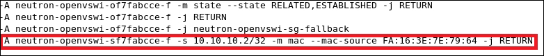
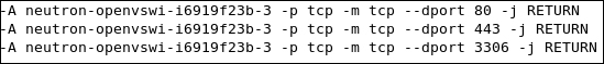
On the other hand, ingress traffic toward the instance is controlled by the neutron-openvswi-icc7474ee6-0 chain, which appears as the following:
The next transit point of our frame Ethernet is the second interface of the patch cable connected to the Linux Bridge, qvb6d6ee47e-04. It next hits the qvbc7474ee6-05 interface attached to the br-int integration bridge, where it performs VLAN tagging/untagging for traffic in both ways. In the next output, you can clearly see that the br-int bridge carries VLAN tagged with the 1 ID, whereas its port interface is the patch-tun patch port, which connects to the tunnel interface:
Before leaving the compute node, the tunnel bridge implies the tagging of the VLAN traffic and encapsulates it into GRE tunnels. Remember that at the br-tun level, flow rules are applied. Basically, flow rules translate VLAN IDs to tunnel IDs. Our second checkpoint will focus on realizing how the flow is applied. The next output command line shows the default flow rules that exist before any instance creation:
Similar to firewall rules, the default set rules of the tunnel bridge imply the dropping of any traffic.
Let's boot an instance and see what is changed:
What is interesting at this point is the first rule: any traffic on tunnel ID 2 tags our frame Ethernet with VLAN ID 1 and sends out port 1. It is important to know that the VLAN ID 1 is a local VLAN with tag 1 of the integration bridge br-tun. The original VLAN ID—for example, the traffic tagged as VLAN 3—is replaced by local VLAN 1 when the traffic reaches the integration bridge. The rule eventually maps the traffic between VLAN ID 1 used by the integration bridge and the tunnel with ID 2 used by the GRE tunnel. However, how does our Ethernet frame move to the integration bridge while the rule has sent it out to port 1? This might be confusing. Do not despair; it should exist in a way that unveils such ambiguity. To do this, we need to investigate the existence of port 1. Let's see what our ovs command line shows in detail:
We can clearly see that the port is designated as a patch interface. Therefore, it will be the next transit point for the Ethernet frame toward the integration bridge. The next rule implies any traffic coming on tunnel 2 within the Ethernet destination 34:e3:44:32:ee:f2 and tags our Ethernet frame with VLAN ID 1 before sending it out to patch-int
The next rule implies traffic coming in on port 1 in_port=1
with VLAN ID 1 dl_vlan=1 and sets the tunnel ID to 2 (actions=set_tunnel:0x2) before sending it out to the GRE tunnel.
Amazing! Then, our frame Ethernet is able to carry on its trip by reaching the network host via the GRE tunnel bridge interface attached to br-tun. The next checkpoint will require the implementation of the flow rules at the network node level, which are similar to the ones of br-tun in the compute node:
# ovs-ofctl dump-flows br-tun
NXST_FLOW reply (xid=0x4):
 cookie=0x0, duration=1239.229s, table=0, n_packets=23, n_bytes=4246, idle_age=15, priority=3,tun_id=0x2,dl_dst=01:00:00:00:00:00/01:00:00:00:00:00 actions=mod_vlan_vid:1,output:1
 cookie=0x0, duration=524.477s, table=0, n_packets=15, n_bytes=3498, idle_age=10, priority=3,tun_id=0x2,dl_dst=fe:13:2e:45:76:dd actions=mod_vlan_vid:1,NORMAL
 cookie=0x0, duration=1239.157s, table=0, n_packets=50, n_bytes=4565, idle_age=148, priority=3,tun_id=0x2,dl_dst=fe:33:fe:ff:ee:3d actions=mod_vlan_vid:1,NORMAL
 cookie=0x0, duration=1239.304s, table=0, n_packets=76, n_bytes=9419, idle_age=10, priority=4,in_port=1,dl_vlan=1 actions=set_tunnel:0x2,NORMAL
 cookie=0x0, duration=1527.016s, table=0, n_packets=12, n_bytes=880, idle_age=527, priority=1 actions=drop
Let's analyze the checkpoints in a nutshell:
Maps multicast traffic on tunnel ID 2 to VLAN 1
Matches traffic on the tunnel destined for the DHCP server at fe:13:2e:45:76:dd
Matches traffic on tunnel ID 2 destined for the router at fe:33:fe:ff:ee:3d, which is an interface in another network namespace
Maps outbound traffic on VLAN ID 1 to tunnel ID 2
The existence of two extra rules, as shown, is due to the usage of the DHCP server and the virtual router device in the network node. We can see this in the next output:
Does this make it more complicated? Well, it might be better to first rekindle the flames and review the namespace concept treated in Chapter 5, Implementing OpenStack Networking and Security, in a nutshell. Remember that a network namespace is similar to a network container, which groups a certain number of Linux kernel facilities in order to form a complete network stack including iptables rules, routing tables, network interfaces, and so on.
A DHCP service is simply an instance of dnsmasq running in a network namespace. It also includes a router, as cited in the preceding example. Let's check out our network namespace:
Here, qdhcp-***** is the named DHCP server namespace and qrouter-**** is the named router namespace.
So, how can we trace our DHCP tap interface in the network node? The best way to do this is by checking the DHCP server's unique address: MAC address. The following command could help us by providing the DHCP namespace:
We can see that ns-f32fc99e-47 matches the tap interface derived from the ovs-ofctl output received previously, which makes sense. The tap interface can be seen as follows:
The next checkpoint is the router interface; using the router namespace, we will identify which interface our Ethernet framework will have to transit:
We have two different interfaces:
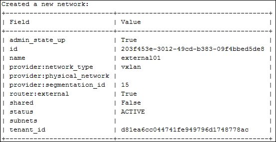
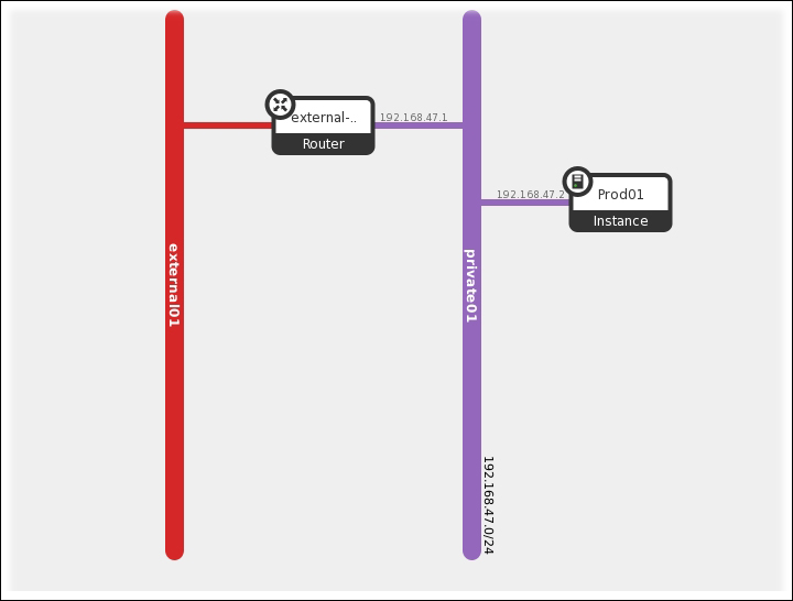
qg-44de398f-aa: This connects the router to the external gateway assuming that 192.168.47.227/28 is an external network
qr-cd366e30-54: This connects the router to the integration bridge, which can be confirmed from the ovs-ofctl output shown previously
Our Ethernet framework is almost connecting to the outside, but before that, we have to tell it which interface it goes from the router. 192.168.47.227/28 is the external network connected to qg-44de398f-aa where traffic will flow through the physical bridge br-ex: